
01Dedicated orientation
Vibratory bowl feeders
Purpose-designed bowls and tooling that separate, orient and present a defined component family to an automated process.
Explore vibratory bowl feeders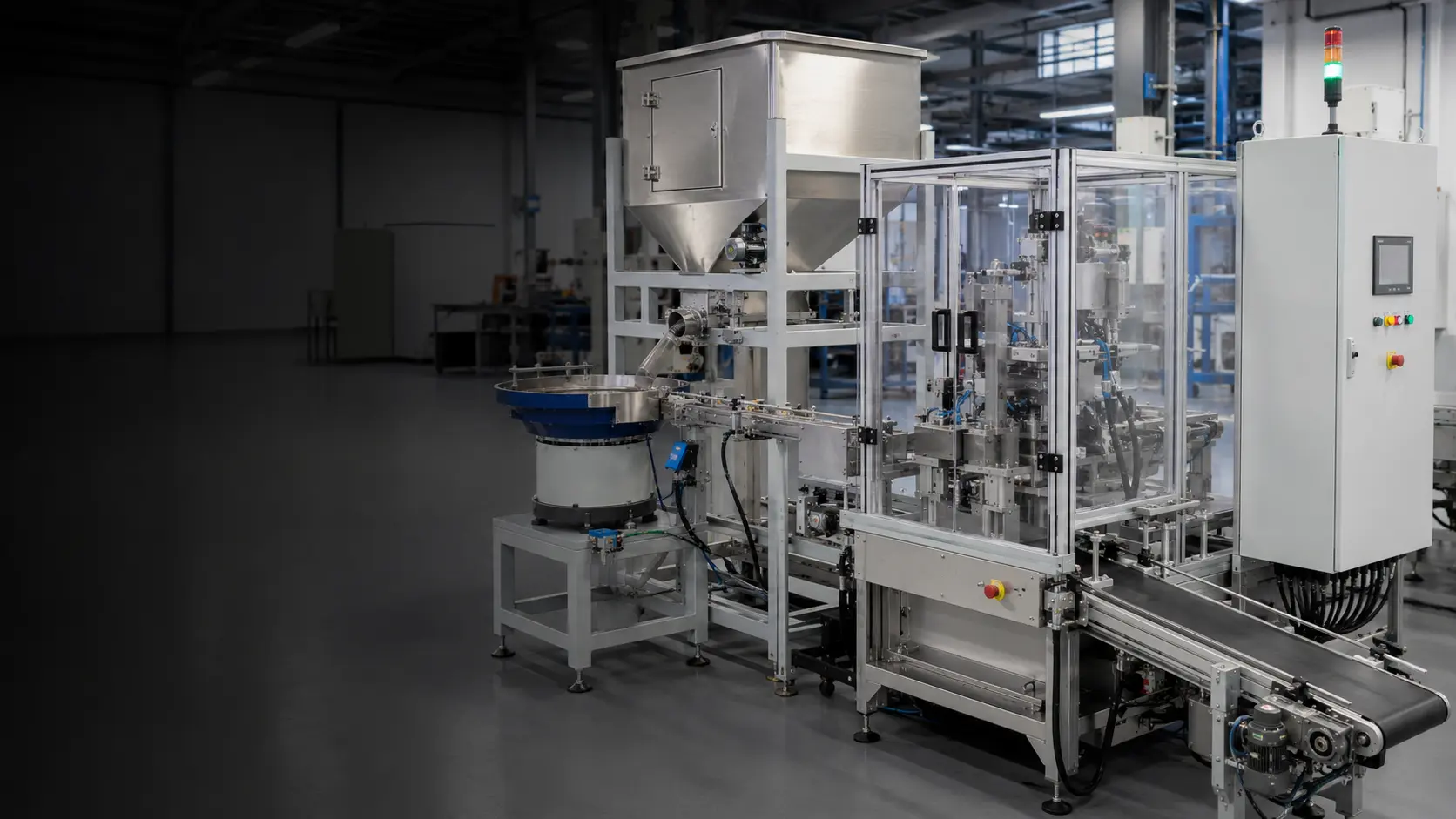
Automated systems that store, separate, orient, inspect and present components reliably to your assembly, packaging or production process.
Discuss your application01844 617223A feeder is only successful when the downstream process receives the right component, in the right orientation, at the right moment.
We bring the complete feed path together: bulk storage, metered replenishment, separation, orientation, inspection, buffering, one-part release and the mechanical and electrical connection to your equipment.
See how complete projects are engineeredDifferent components demand different handling. We keep the technology choice open until geometry, behaviour, required output and changeover model are understood.
Compare every system
Purpose-designed bowls and tooling that separate, orient and present a defined component family to an automated process.
Explore vibratory bowl feeders
Rotary feeding platforms for suitable caps, closures and robust components where smooth, high-flow presentation matters.
Explore centrifugal feeders
Low-vibration step lifting for components that benefit from quieter handling, reduced recirculation and a larger useful size range.
Explore step feeders
Programmable feeder platforms, controlled lighting, machine vision and robot picking for variant-rich production.
Explore flexible feeding systems
Tracks, buffers, sensors and one-part release mechanisms that connect the feeder to the production cycle.
Explore linear feeders & escapements
Bulk storage and metered replenishment that extend operating autonomy without overloading the orientation device.
Explore bulk hoppers & elevatorsTell us what the component is, how it must leave the system and how your machine consumes it. From there we can identify the questions, trials and interface details that matter.
We will show a sensible technology to investigate first—not a final specification.
Explore project routes for random-bin presentation, automatic fastener delivery and verified component batches.
Compare every feeding technology →2D or 3D vision, robot handling and controlled replenishment for randomly presented parts.
Explore robotic bin picking →Present screws, nuts, washers and inserts to drivers, robots, presses or pick points.
Explore screw feeding →Feed, detect and discharge defined quantities to bags, kits, cartons or assembly processes.
Explore counting systems →From high-volume closures to precision terminals and assembly components, the same rule applies: prove the real part in the required condition.
Explore all applicationsClips, connectors, seals, plugs, terminals, fasteners and precision mouldings for assembly and test stations.
View application →02Controlled feeding of closures, diagnostic components, devices and moulded parts where handling and cleanability matter.
View application →03Orientation and presentation of terminals, connectors, housings and small components to assembly, insertion and test equipment.
View application →04Screws, nuts, washers, rivets and threaded inserts presented to drivers, presses, assembly machines and robots.
View application →05High-flow feeding and orientation for screw caps, snap caps, pumps, lids, overcaps and other packaging components.
View application →06Application-engineered feeding for moulded, pressed, machined and cast parts across general manufacturing.
View application →
A fast feeder is not useful if the host machine cannot receive its output reliably.
We define discharge height, orientation datum, track pressure, buffer capacity, sensor logic, escapement timing, I/O, fault recovery and safeguarding as part of the project—not as an afterthought.
Use these guides to compare technologies, prepare representative samples and define an acceptance test before committing to a design.
Compare bowl, centrifugal, step and flexible feeding against the behaviour of your component.
Read guide →Specification checklistCapture orientation, sustained rate, loading, inspection, interface and acceptance requirements.
Use checklist →Engineering guideTrace faults from bulk level through orientation, buffer and final machine hand-off.
Read guide →Useful starting points. Final recommendations are based on your component, presentation requirement and machine cycle.
An automated parts feeding system stores bulk components, separates them, establishes the orientation required by the process and presents accepted parts at a controlled rate. A complete system may include a hopper, bowl or flexible feeder, linear track, sensors, vision, buffering, an escapement, controls, guarding and the final machine interface.
There is no universal best feeder. Vibratory bowls suit many dedicated component families; centrifugal feeders can suit high-speed stable parts; step feeders are useful for quieter or larger-component handling; and flexible vision-guided systems can suit frequent variants. Selection begins with the real component, required presentation and sustained machine demand.
Cost depends on component behaviour, orientation complexity, target rate, number of variants, bulk autonomy, inspection, controls, guarding and the downstream interface. A credible budget is prepared after a component and application review; a catalogue feeder price alone rarely represents a complete production system.
The achievable sustained rate is application-specific. Part geometry, stability, recirculation, inspection, buffer length and the release mechanism all affect accepted output. The correct figure is demonstrated under agreed test conditions with representative production components.
Representative production samples are strongly recommended and may be essential. Drawings establish dimensions and tolerances, but physical trials reveal friction, bounce, nesting, tangling, surface marking and behaviour at the required speed.
Sometimes. Closely related variants may share adjustable or change-part tooling. A flexible feeder may be more appropriate for wider variation. The solution depends on geometric differences, required changeover time, production mix and whether the same discharge presentation is possible.
Send a photograph or drawing, target rate and required orientation. We will help identify the most credible feeding route.
A buffer holds usable, correctly oriented components between feeding and consumption. Begin with the receiving machine’s demand pattern and the interruption the buffer is intended to bridge. Count parts that can actually be released to the machine, not every loose component visible upstream.
For a constant demand, a simple planning quantity is demand in parts per minute multiplied by interruption time in seconds, divided by 60. As an illustrative calculation, 60 accepted parts per minute for a 20-second interruption needs 20 available parts before any application-specific allowance. This is a planning example, not a feeder performance or guaranteed buffer specification.
Then check whether that quantity can be held without losing orientation, damaging surfaces or creating excessive pressure at the escapement. A long queue is not automatically a better solution. Include how parts enter the buffer, how occupancy is detected and how upstream feeding responds when the receiving machine stops.
Recovery matters as much as initial capacity. The feeder must replenish the used buffer while the host resumes consuming parts, under the agreed conditions. Challenge empty and full states, a stopped host, an interrupted release and restart after replenishment. Record accepted deliveries and the recovery sequence during representative trials.
Linear feeders and escapements · Plan representative component trials
A feeder that handles the largest production run may still be a poor match for the weekly mix. Compare the complete operating schedule, including changeovers and small batches, alongside the sustained accepted output.
Explore complete parts feeding systems — read the detailed guide